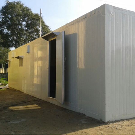
Shelters
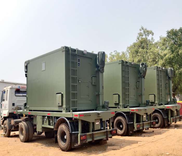

Nomenclature: Standard ISO 20 ft Shelter
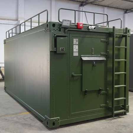
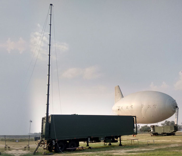
These lightweight, highly versatile 20' ISO units can be utilized as command & communications centers, UAV post, electronic warfare maintenance facilities or other applications. The Shelters will be of construction All Aluminum Structural or All welded or customised.
Military Specifications:
ASTM E1976, ASTM E1977, ASTM E1978
ISO/ANSI Specifications: ISO 668, ISO 1496/1, ISO 1161, ISO 3874
Exterior Dimensions: 96 in. high, 96 in. wide, 238-1/2 in. long
Service Life: 15 years service, 20 years storage
Temperature Extremes:
Operating: -65° F to +125° F plus solar load
Non-operating: -80° F to +160° F
Heat Transfer:
One-Side: 0.35 BTU/hr. ft 2/f
Roof Loads: Withstands a snow load of 40 lbs/ft2
Performance Specifications: Weight:
15 years service, 20 years storage
Wall Attachment Loading: Potted Inserts installed anywhere withstand 455
Kg (1000 pounds) tensile loads.
Water tightness: Double gaskets at all seams for protection against
rainfall of 6 in/hr
Optional Items: Skids: Three full-length replaceable skids
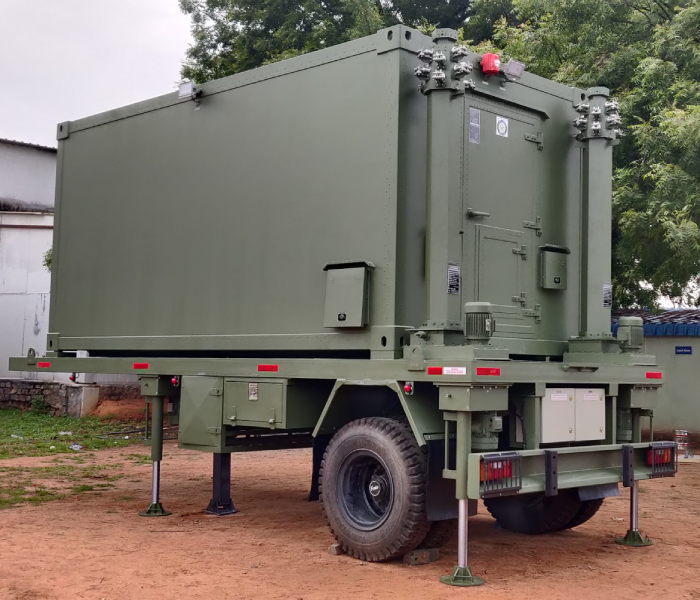
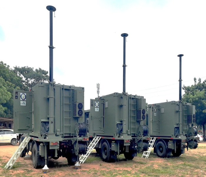
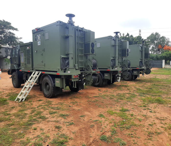
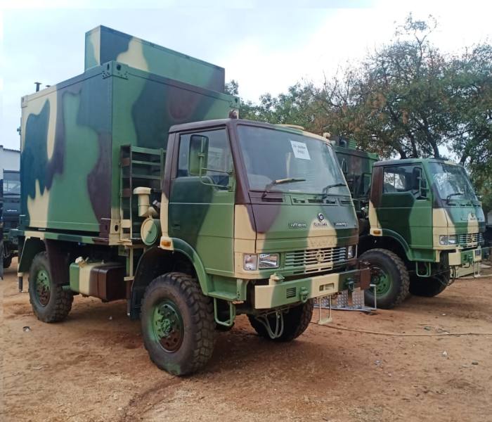
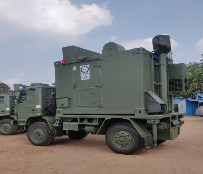
Nomenclature: S-280C/G
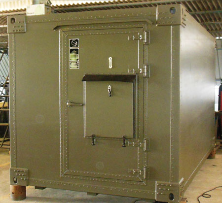 The S-280 shelter provides optimum performance under the most demanding field conditions.
Lightweight, high strength, insulated and all weather, this shelter satisfies general
purpose applications for housing communications and other transportable electronic
equipment. Rugged inside and outside, the S-280 is equipped to withstand adverse weather and
terrain, in addition to a high level of interior traffic.
The S-280 shelter provides optimum performance under the most demanding field conditions.
Lightweight, high strength, insulated and all weather, this shelter satisfies general
purpose applications for housing communications and other transportable electronic
equipment. Rugged inside and outside, the S-280 is equipped to withstand adverse weather and
terrain, in addition to a high level of interior traffic.
The S-280 shelter is of foam-and-beam sandwich panels which consist of a polyurethane foam core, aluminum skins and a framework of high strength aluminum alloy extrusions. Structural strength is assured by orientation of the floor and roof beams in transverse direction. This "barrel hoop" construction provides the ability to withstand drop tests and high roof loads. Foam and beam panel construction provides high strength to weight ratios and facilitates ease of modification, repair, and maintenance. Thick inner and outer floor skins (0.050 in.) lend added strength to withstand increased personnel or equipment traffic. Shelter corners are reinforced to accept leveling jacks and to withstand side load imposed by high wind velocities.
The original S-280 shelter was reviewed under the U.S. Army Product Improvement Program. As a result of this review and the DoD standardization of shelter programs, the current S-280 was developed and reflects valuable construction changes and nomenclature model redesignation. The result is an improved, tested, standard shelter.
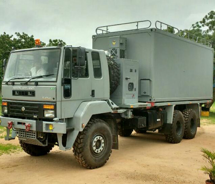
The S-280 can be transported via military truck, helicopter, cargo aircraft such as the C-130, M720 and M832 mobilizers, and by rail and ship
Performance Specifications:
Specification MIL-S-55286E
Roof Load:
Snow and Ice: 75 lbs./sq. ft.
Personnel and Equipment: 660 lbs. over a 2 sq. ft. area
Floor Loads: 2,500 lbs. over 3 sq. ft. area without permanent deformation
Member Loading: Wall, roof, and floor tensile load 2,000 lbs. followed by 100 inch-pounds torque load (5/16"-18 inserts)
Temperature Extremes:
Operating: -65° F to +125° F plus solar load
Non-operating: -80° F to +160° F
Heat Transfer: U-factor 0.28 BTU/hr./sq. ft./°F RFI Shielding: With addition of RFI modification kit, attenuation of 60 dB minimum over 150 kHz to 10 GHz for electric and magnetic fields and plane waves measured IAW MIL-STD-285
Lifting Eyes: Four (4) eyes with 3 in. inside clearance. 14,400 lbs. tensile load per corner in any direction
Towing Eyes: Four (4) eyes with 2 in. inside clearance. 14,400 lbs. tensile load per corner in any direction
Features:
Skids: Three (3) full length replaceable shock absorbing type
Roof Access Steps: Three (3) recessed folding steps in sidewall and one roof handhold
Combination lifting/tie down sling to facilitate handling
Options: RFI modification kit
Mobilizer adapter kit for shelter/transporter interface
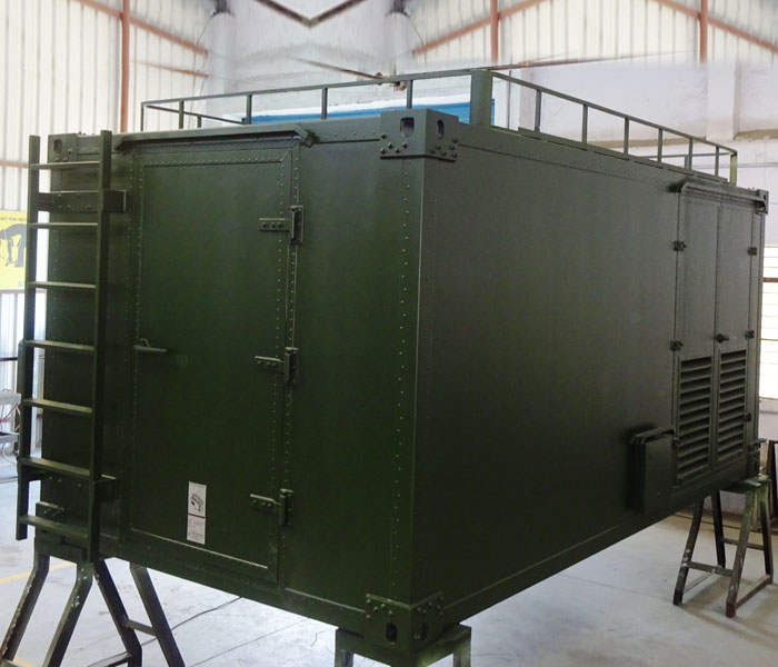
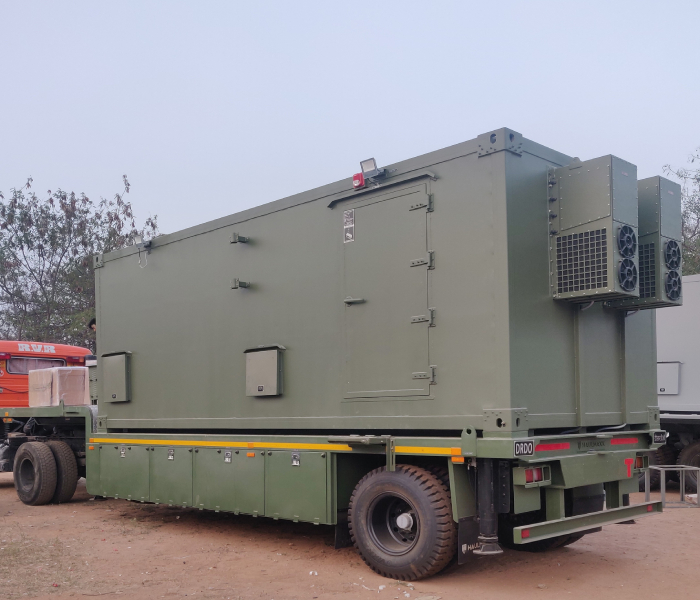
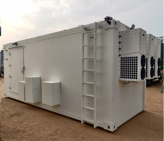
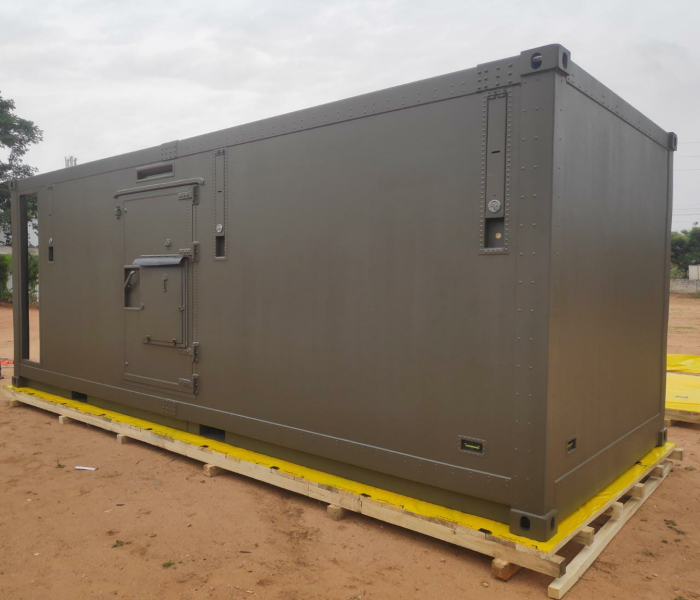
Carbon Composite Shelter
Highlights:
- Carbon Fiber offers 2 to 5 times more rigidity than aluminum and steel.
- For one-direction Carbon Fiber, its stiffness is 5-10 times more than steel or aluminum (of the same weight).
- The component made from Carbon Fiber of the same dimensions will be 50% lighter than an aluminum one and more than 5 times lighter than a steel one.
- A component made from standard Carbon Fiber of the same thickness as an aluminum one will offer 31% more rigidity than the aluminum one and at the same time weight 50% less and have 60% more strength.
- Carbon Fiber will reduce its weight by 50%. Replacing steel with Carbon Fiber will reduce the weight x 5 times.
- Carbon Fiber shows nearly zero heat expansion it is widely used in devices including 3D scanners.
- Carbon Fiber is a material with heat expansion x 6 times less than aluminum and more than 3 times less that steel.
- Carbon Fiber and epoxy resin is a material with heat conductivity x 40 times less than aluminum and 10 times less than steel.
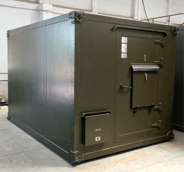
CARBON COMPOSITE MILITTARY SHELTER - KEY FEATURES
Construction
Shelter is constructed of foam and beam sandwich panels which consist of a polyurethane foam core, carbon composite skins and a framework of high strength FRP tubes extrusions. Structural strength is assured by orientation of the floor and roof beams in transverse direction.
Specification
MIL-S-55286E, ASTM E 1975
Specification
MIL-S-55286E, ASTM E 1975
External Dimension
3400 L x 2210 W x 2194 H in mm
Weight
550 Kgs
Payload
5000Kgs
Roof load
Snow load of 40 lb/ft2 (200 kg/m2)
Personnel load of 660 lb (300 kg) static over 2 ft2(0.2 m2).
Floor load
Uniform load of 65 lb/ft2(320 kg/m2).
Concentrated load of 2,000 lb (900 kg) over a 4-ft2(0.4-m2)
Temperature extremes
Operating: -30oC to +55oC
Non-operating mode: -40oC to +70oC
Heat transfer coefficient
6 W/m K
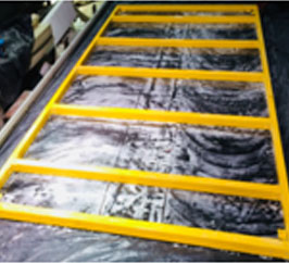
RFI shielding
Attenuation of 60 db minimum over spectrum of 150KHz to 18 GHz for electric and magnetic fields and plane waves as measured IEEE 299
Water tightness
Completely water-tight tested to simulated rainfall as per ASTM E 1925 & MIL STD 55286 E
Transportation
The shelter can be transported by military truck, helicopter, cargo aircraft such as the C-130, by rail and ship
Application
For Saline seashore & High Altitude terrain conditions
Ultra light Carbon Composite Shelter for Saline & High Altitude conditions
| Parameters | Carbon | Aluminum | Steel |
|---|---|---|---|
| Dimensions | 20ft(L)x8ft(W)x8xft(H) | ||
| Weight in kgs | 950 | 1450 | 1850 |
| Floor load kgs | 5000 | 3200 | 3200 |
Designed & Manufactured for the first time in the country
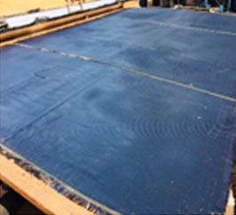
Carbon Fibre Sheet
FRP structural grid
Test & Trials
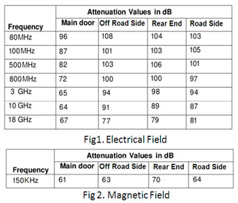
EMI Shielding Attenuation Results Meets the curve as per ASTM E 1925
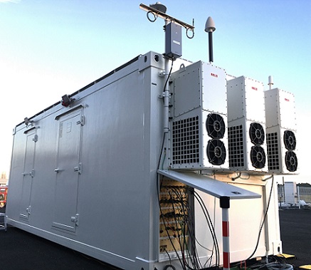
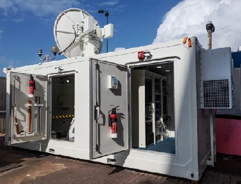
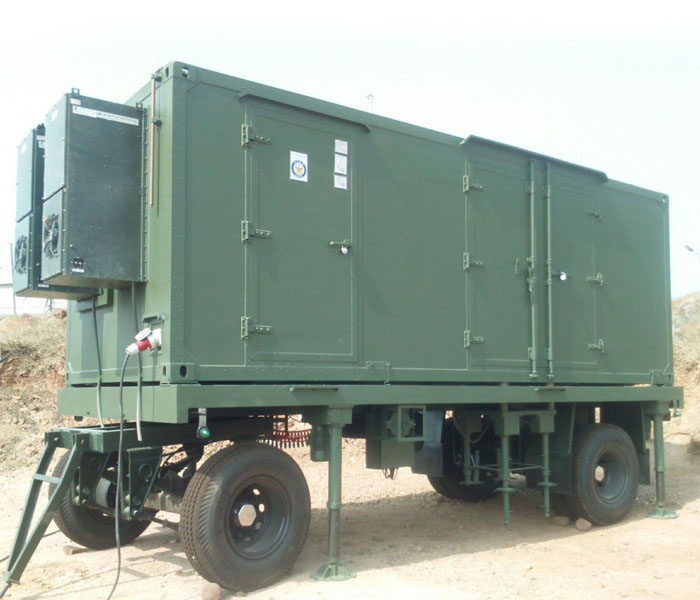
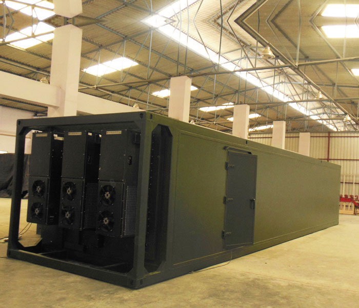
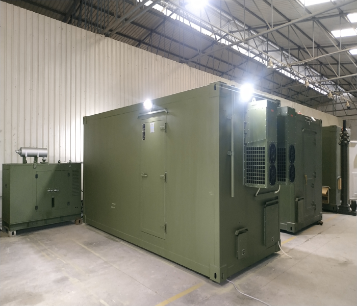
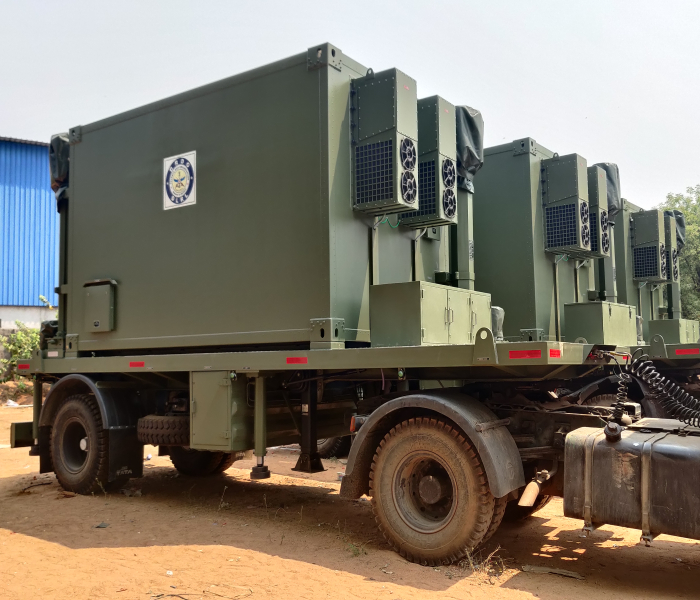
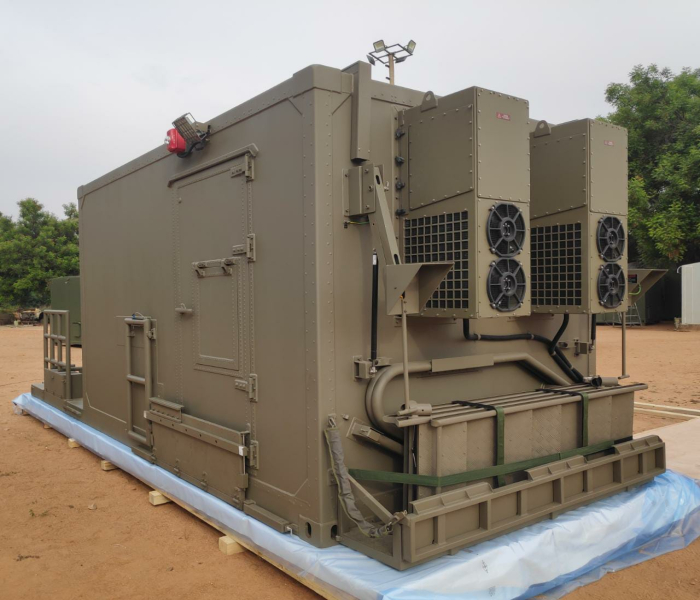
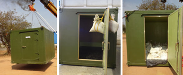
Non- Standard EMI/EMP Shelters
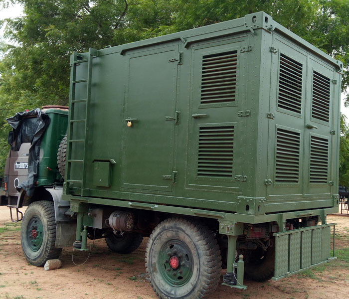
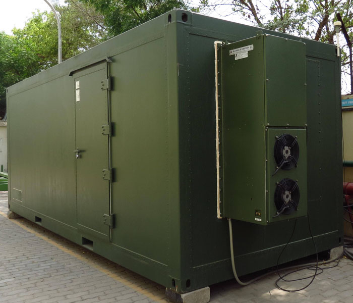
All these shelters are tailored and meets the customer's specific requirements. Generally, these shelters vary in length, width and height. The construction of these shelters vary depending upon the floor payload capacity and their application. The shelters can be manufactured with very light weight meeting the payload criteria.
These shelter are EMI/EMP Shielded and also used for mobile application
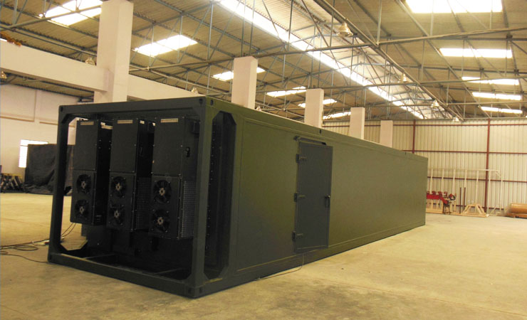
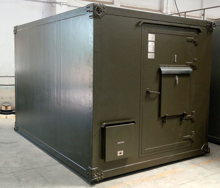
Shelter
These shelters are manufactured using sandwich panels constructed with composite foam and beam configuration. The Shelters will be of construction All Aluminum Structural or All welded or customised. The panels will be formed by hot pressure bonding technique in a press. The assembly of the shelter will be realized by using high quality blind Aluminum rivets to achieve desired EMI shielding results. The structure will be provided incorporating the Aluminum alloy ISO Corner blocks/corner fittings are used for lifting and integration to the trailer. The ISO corners made of suitable Aluminum Alloy will confirm to ISO 1161 and have gone through Ultrasonic test satisfactorily. . All structural and reinforcement Aluminum alloy angles tubes etc are to confirm to 64430 grade.
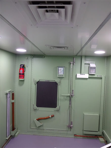
The shelter will provide mounting points for the fitments like the 19" Equipment racks, MIL Grade Air Conditioning Unit, NBC System, UPS system, DG sets, wall cabinets, operator tables, etc. The shelter will form a hermetically sealed area providing the highest levels of, sealing against ingress of weather agents like rain and dust, shielding against electromagnetic interference effects and, corrosion resistance for extended periods of time in deployment.
Efficiently double vault designed I/O panel will be provided at convenient locations for outdoor / indoor interface. The connector mounting plate will be of the cascade type, having 2 rows of inclined surfaces for connector mounting. These connector plates will be riveted to the periphery of the cutout for maintaining the shield integrity. The I/O panels will be closed and locked during transportation.
Main door will have 3 point lock mechanism and should be light weight. The emergency door is located inside main door with a provision for allowing airflow if required by opening cover.
False Ceiling:
False ceiling will be provided 150-200 mm below the roof panel of the shelter. AC ducts will run below roof panel and these ducts are of GI/Aluminum material which are equipped with melamine foam and performed sheet. Aluminum Composite Panels will be laid for internal aesthetics.
Conditioned air from the AC system will be distributed around the shelter. The air will be delivered with dedicated air ducts. The design of the ducts will allow circulation and cooling of the equipment inside the equipment racks.
The ducts will be designed to prevent short circuit air circulation and Selection of Diffusers will be provided
False Flooring
The manufacturing of special designed false floor with antistatic access floor tiles.
The access floor tiles will be mounted on zinc plated steel Pedestals consisting of anti-vibrational head cap.
The tiles supporting channels between Pedestals will be fitted with screws, plain washers and lock nuts to prevent loosening. It will facilitate easy removal/reassembly for maintenance purposes.
The false floor will be provided with an antistatic non slip mat. Tile remover will be provided for maintenance aspect.
Ascentech provides complete Electrical package
- The Electrical system of the shelter will be controlled through a power distribution board. The design and construction of the PDB will comply with the requirements of IEC 439 part-1. The PDB will be installed in cabinet. The degree of enclosure to be IP 43.
- Power distribution panel of reputed make Hensel/Schneider will consist of suitable capacity of single /Double/Three pole MCBs in required rating and numbers, individual switches for lights, volt meter and ammeter will be provided.
- The PDB will include the following main control components:
- Main Circuit breaker
- Surge Arrestor
- Illumination Main Power ON/OFF siwtch
- Emergency OFF switch and relay
- Power Control multi-meter
- Phase presence indicator lamps
- Mode display
- All the controls will be located on front panel.
- All subsystems internal and external to shelter will be electrically connected / integrated
- EMI Power and Signal filters will be used at the Point-of-entries to maintain the required shielding effectiveness of the shelter.
- The Power and Signal inputs will be routed via EMI Filters to maintain the specified shielding characteristics of the shelter.
Illumination system
- The lighting will be designed according to the recommendations of MIL-STD-1472F.
- Power cables to lighting fittings will be routed in cable ducts on the shelter ceiling.
- The lighting power cable ducts will be as short as possible.
- Lighting power cable ducts can lead power to both external and internal light fitting.
Grounding
Shelter grounding
- The shelter will be grounded to a grounding point
- The following grounding will be implemented in the shelter:
- Grounding studs at Power & Signal I/O panels
- Earthing rod
- Common grounding strip
- Metal frames of the equipment racks
Lightning conductor
- A lightening conductor will be installed on the shelter to prevent lightening hitting the shelter directly.
- The Lightening conductor will be disassembled and stored in an external toolbox or secured to one of the external walls.